This is a article written by Daniele Cappa (IW1AXR) and published in Radio Elettonica in March 2009. It was originally written in Italian. This is a translation to english. I have adjusted the wording because, direct translations make reading difficult. Hopefully, I have kept the authors intent intact.
 Change to an SM2 and an SM5 ICOM by Daniele Cappa (IW1AXR), Radio Elettonica 3/2009
 |
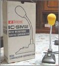
The SM2, SM5 are two small desktop microphones. What follows is valid for the models SM2, SM5 and SM6, all aesthetically identical to each other
It is always pleasant to have in his hand an object that has on the shoulders a few tens of years, even more if they have left on the object only of the slight signs ... These are dated models, the SM6 it is the most recent and its production dates back to the end of the 80s. The first models are still marked INOUE, from the name of "Mr. Icom ", Tokuzo Inoue, JA-3FA.
Founded in July 1964, the INOUE EIectric Manufacturing Co. Ltd, in June of 1978, changed the name of the company to Icom, an acronym for Inoue COMmunications. Since "Mr. Icom ", has always occupied the office of president of society; only recently, in 2006, this has passed of hand.

So the production of the three "brothers" models extends to about 15 years, probably from more.
Some are available on the web schemes, which seem to be original from the manufacturer, but that they do not reflect the content at all of the two microphones examined, certainly back from innumerable modifications and repairs. Neither more versions have been produced identical to each other only in aesthetics: SM2, SM5 and SM6 are, in the mechanical part, absolutely identical (separate label obviously). It is likely that specimens of the same model are actually versions that they could be internally very different.
The triggering cause it has brought to these lines was the purchase of an SM2 on Ebay. The aesthetic conditions are more than that decent, up to be still in the original packaging, less electric ones. The microphone is working, but it has been the object of changes or repairs that they have completely changed characteristics and that in fact they strongly limit its use.
 Powering the Icom microphones
 |
Even though the first two models were in produduction until the early 80s, they all have a peculiarity that Icom still includes in the current production. This deals with the pre-amplifier power supply Rather than power the preamp and microphone from the "+8V", power is obtained from the audio wire.
Given the age, at least the first two models were designed for RTX in production until the early 80s, they all have a peculiarity that Icom still uses today in the current production. It deals with of the preamplifier power supply of the microphone, and endowment also standard for microphones from palm already starting from the end from the 70s. The power is flow to the internal preamplifier to the microphone not from the usual pin "+8V", but from the wire that leads the microphone signal.

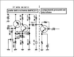
In Figure 1 we see the scheme of the entry stage of the microphone of the IC211 (VHF allmode in the mid-70s): the left side has been copied from the wiring diagram of the transceiver, while the part a right of the dotted line "Could" be that of the microphone. It's just an example, in fact no value of i is reported components. As is easy to note the R84 (4.7KΩ) and C70 (4.7 µF) they are the resistance respectively of collector and the condenser decoupling of the transistor of the preamplifier that is located inside the palm microphone shell! Caution however ... the IC211 quoted was equipped standard of a palm microphone dynamic type, without the preamplifier, even if among the his accessories featured the microphone table lamp SM2.
So the Inoue, even earlier to become Icom, he had expected an ingenious system to feed the preamplifier of the microphone without adding any power cord to the microphone, and consequently without change the connector pinout of the microphone then it was the usual (!) 4 pole.
The same system is still valid today and the latest RTX of Icom home still have this possibility, even if already starting from the SM8 the power supply to the microphone table was supplied by the pin 2 of the microphone's 8-pin socket.
However, after many years it can turn out to be useful to use one of these microphones on RTX not of Icom home. The solution is trivial, just provide the preamp the components necessary for the operation, or change the original circuit.
We will evaluate both situations exploiting an SM2 to which it is the preamplifier has been rebuilt and he was given the power external and an SM5 to which it is the pre leaving was rebuilt but the compatible power supply with the original.

The problems do not end here ... the oldest transceivers that they had this chance and they were equipped as standard with a microphone preamplified from the palm, then IC290, IC490, IC255, etc., in practice the series after 211 and characterized by digital harmony, LED display, but already with the 8-pin microphone connector (so with i UP / commands DOWN on the microphone). they a sensitivity very low on the microphone socket, or they require a lot audio signal to produce a modulation acceptable… If we try to use one of these microphones on an existing RTX the results are devastating: one modulation practically unmanageable combined with whistles that reach unacceptable levels.
In fact, if we look at the microphones produced subsequently, as the cited SM8, we see that on the lower part, in addition to the trimmer for the output level is present a deviator that allows the choice of two output levels (high it's short). Given that the resistance of pre-amplifier manifold it is not possible to insert in the radio an output attenuator, as certainly some readers he will have thought.
Therefore we propose two "alternative" preamps a the original one present in the three mentioned models, usable both in the case of failure of the original, such as in case of use on different RTX, up to use on RTX level lower, and therefore lacking of commutations, as they are often the CB RTXs equipped with a socket of the 4-pole microphone. In all Icom microphones indeed command of the PTT is carried with two wires, the command and the mass that is though duplicated also on the screen of the microphone signal wire. The connection of the two masses together directly in the microphone therefore frees a cable which can be used for the switching of PTT to RX (required in almost all RTX CB). The power supply to the preamplifier of the microphone can be realized directly in the RTX, obtaining an "Icom-like" system that allows one to use one these microphones practically on any transceiver, or withdrawing +8 V and making so the microphone compatible with any other brand.
 The preamp for Icom ...
 |
In my SM5 there was a pre to three transistors coupled in continues that generated a rustle far beyond the acceptable. Transistors employees were three 2SD661, that have been unsoldered, as well as most of the components original. I preferred to take advantage of it the small printed circuit original, readjusting it to mine project, which to design one new or mount it all on one small millefori.
The chosen scheme is suitable for three-wire condenser capsules, but also to examples of a dynamic type or condenser capsules two wires only.


It does not provide a preamp excessive, therefore it results not suitable for use on Icom anymore dated (the cited IC290, IC490 etc.), while for the most recent production provides such a signal that the level regulation a half is already high enough!
The biggest problem in schemes of this type is the regulation of the audio level: not being possible to do it on the exit of the stadium, where it would be more logical, it is necessary to insert it between the microphone and admission. An amplification excessive therefore leads to noises and rustles that do not come attenuated by the regulation of the level.
We come to us, the scheme is trivial and known, a single emitter stage common with the polarization base obtained from the collector of the transistor; being the power supply inside the transceiver it is not possible to use the classical polarization with the partition in base. The thing it is still valid: this configuration produces a mild negative reaction leading to a automatic gain control and increases the stability of the Stadium.
We have a wide selection of components, the transistor can be "Almost anything": it must be a silicon NPN, for switching or for low signals. Therefore BC107, 108, 109, 237, 238, 239, 547, 548, 549 ... 2N2222, 2N3904 ... could be fill entire pages only by listing a part of them.
The input trimmer is that original of the SM5, as well as the input capacitors and that filter to the power supply of the capsule. On the exit towards the radio and on the entrance to the capsule there are two impedances RF (a simple bead of ferrite inserted in a rheophorus) that have not been reported on the scheme. Their absence does not prevent the operation of the pre, bad do not, so le I left them in their place.
| List of components to change with Icom style power supply | |
|---|---|
| R1 | 1 MΩ 1/4W |
| R2 | 270 Ω 1/4W |
| R3 | 3.3 KΩ (SM5 original) |
| R4 | 4.7 KΩ (SM5 original) |
| R5 | from 1 to 4.7 KΩ |
| R6 | 1.5 KΩ, (R3/2 if used) |
| C1 | 4.7µF/16V |
| C2 | C3 = C5 = 10 µF/16V |
| C4 | 1 to 10 µF/16V |
| Q1 | NPN transistor BC548, or similar. |
| List of components to change with external power supply | |
|---|---|
| R1 | 1800 Ω 1/4W |
| R2 | 100 KΩ 1/4W |
| R3 | 22 KΩ |
| R4 | 2200 KΩ |
| R5 | trimmer 10 KΩ |
| C1 | C2 = C3 = 10 µF 16V |
| C4 | 1 to 10 µF 16V |
| Q1 | NPN transistor BC548, or similar. |
As is typical in these schemes needs must be adapted of the radio to those of the operator; therefore to completion completed may prove necessary some substitutions. A stamp of too much metallic voice is attenuated by the replacement of the capacitors interested in the signal (C1 and C2 and any C4 and C5) with capacity elements greater. If on the contrary it is found an excessive presence of low tones it is good to carry out the replacement of the same capacity with elements of value lower, even an order of greatness and where it is possible is an excellent idea to move from elements of electrolytic type to ceramic multilayer, chosen more for the small size than for others parameters.
 ... and the general purpose one
 |
Here, too, nothing new, a only common emitter stage, this time with voltage divider for the basic polarization, collector output on a trimmer which adjusts the output level. The feeding of the capsule e of the pre are derived from + 8 V present on the microphone socket. In truth this object was intended for a production RTX Yaesu which only provides +5 V on the microphone socket. obviously everything works equally good on any transceiver you want to use it.
I have not repeated the change for the feeding of the capsule a only two threads because it is absolutely identical to that of the other version, as they are completely similar evaluations about the use of other transistors and the possible adjustments to the values ?? of the ability on the signal path.
Also in this case the assembly it was made using the original print, readjusting it to new needs. THE capacitors are all from 10µF, they were left in its place the original ones. Also the transistor BC109c is one of the two present on the base: certainly it is not about the originals used from the manufacturer.
For the modification of the SM2 it is necessary the replacement of the trimmer original, is a sample from 500 Ω against the 10KΩ used, while in the case of the SM5 this is the value of the original component.
For feeding it is necessary draw a wire from the cable goes to the transceiver. As expressed before you can get it unsoldering the PTT cable, Red; in its place we will weld a few inches of thread towards mass (to be welded on the printer). Now the black thread that first it was the mass of the PTT it became the command of the PTT, that red now free will be soldered on the microphone connector on the pin of supply while the conductor white will be headed by the trimmer through the condenser of decoupling C1 and it is the output of the signal towards the transmitter.
What you read is the result of the change of the SM-2 of Marco, IW1DGK, to which he followed the modification of my SM-5 lying abandoned for years in a wardrobe since the abandonment of the old Icom had of prevented use. It's obvious that the two proposed operations They are valid for both models: the choice of which to achieve is exclusively linked to the use a which microphone is intended for seviziare.

It's worth spending two words on the prices of the used ... Guido, who takes care of the quotations reported on www.radioamateur.eu reports values ??between 50 and 80 euros for SM5 and SM6 models. It's obvious that a lot depends on conditions of the object, particularly aesthetic ones. As we have seen the functionality is easily recoverable, but the aesthetics of these bad microphones it lends itself to a restoration. The operation that I have illustrated several times in this magazine it is valid only for the small base in metal. The stem and the head are in fact, chrome and the only intervention possible is a good cleaning. The mechanical part is reduced to button for PTT that commands a microswitch with a common appearance and from which they should not emerge problems. The are valid usual recommendations: if you buy on the net and if our intention it is the purchase of an object to restore, do not be in a hurry, be wary of those who "avoid" to show us a specific detail of the object and, of course, spend the least possible!

|
